400 Series Hydraulic Cylinder Rendering

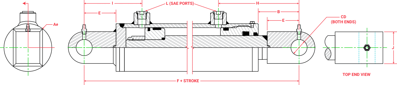
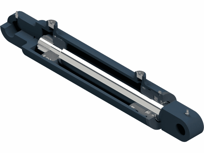
400 Series Cylinder Features


  • Lug style base and rod mounts
  • 2500 PSI Standard Duty Type
  • Cold drawn (high impact) 75,000 min.yield D.O.M. tubing
  • Ground & polished, hard chrome plated rods (75,000 min. yield)
  • Welded style construction certified to A.W.S. B2.1
  • Internally threaded head design with buttress threads
  • Highest quality seal configurations compatible with petroleum base fluids
  • Ductile iron head gland & piston
  • Piston utilizes wear bearings
  • Nylon inserted lock nut
  • Standard paint; black primer

Pre-Engineered Hydraulic Cylinder Configurations

400 Series Cylinders Diagram

Bore Rod A B CD E F G H I J K L Part #
1.50 .75 2.00 2.12 .750 1.50 8.00 .75 4.06 2.81 .75 .75 #4 404-**.**
1.00 2.00 2.00 .750 1.50 8.00 .75 4.06 2.81 1.00 1.00 #4 406-**.**
2.00 1.00 2.50 2.62 1.00 2.00 9.50 1.00 4.88 3.38 1.00 1.00 #6 410-**.**
1.12 2.50 2.75 1.00 2.00 9.50 1.00 4.88 3.38 1.25 1.25 #6 412-**.**
1.25 2.50 2.50 1.00 2.00 9.50 1.00 4.88 3.38 1.25 1.25 #6 414-**.**
2.50 1.25 3.00 2.75 1.00 2.00 9.75 1.00 4.88 3.62 1.25 1.25 #6 418-**.**
1.50 3.00 2.56 1.00 2.00 10.00 1.00 5.06 3.69 1.50 1.50 #6 420-**.**
3.00 1.25 3.50 2.81 1.00 2.00 10.25 1.00 5.25 3.75 1.25 1.25 #8 424-**.**
1.50 3.50 2.69 1.00 2.00 10.25 1.00 5.12 3.88 1.50 1.50 #8 426-**.**
1.75 3.50 2.69 1.00 2.00 10.25 1.00 5.12 3.88 1.75 1.75 #8 428-**.**
2.00 3.50 2.69 1.00 2.00 10.50 1.00 5.38 3.88 2.00 2.00 #8 430-**.**
3.50 1.50 4.00 3.06 1.25 2.50 11.25 1.25 5.50 4.50 1.50 1.50 #8 434-**.**
1.75 4.00 3.06 1.25 2.50 11.25 1.25 5.50 4.50 1.75 1.75 #8 436-**.**
2.00 4.00 3.06 1.25 2.50 11.25 1.25 5.50 4.50 2.00 2.00 #8 438-**.**
4.00 1.50 4.50 3.19 1.25 2.50 11.50 1.25 5.62 4.62 1.50 1.50 #8 442-**.**
1.75 4.50 3.25 1.25 2.50 11.75 1.25 5.69 4.81 1.75 1.75 #8 444-**.**
2.00 4.50 3.25 1.25 2.50 11.75 1.25 5.69 4.81 2.00 2.00 #8 446-**.**
2.50 4.50 3.25 1.25 2.50 12.00 1.25 5.94 4.81 2.50 2.50 #8 448-**.**
4.50 1.75 5.00 3.12 1.25 2.50 12.00 1.25 5.56 4.94 1.75 1.75 #8 452-**.**
2.00 5.00 3.12 1.25 2.50 12.00 1.25 5.56 4.94 2.00 2.00 #8 454-**.**
2.25 5.00 3.12 1.25 2.50 12.00 1.25 5.56 4.94 2.50 2.50 #8 456-**.**
5.00 2.00 5.62 3.25 1.50 2.50 12.50 1.50 5.69 5.31 2.00 2.00 #8 460-**.**
2.50 5.62 3.25 1.50 2.50 12.75 1.50 5.94 5.31 2.50 2.50 #8 462-**.**
3.00 5.62 3.25 1.50 2.50 12.75 1.50 5.94 5.31 3.00 3.00 #8 464-**.**

Pre-Engineered Cylinder Drawing Program

Instantly customize and print detailed prints of our 400 Series Pre-Engineered Cylinders.

Try It Now

Ordering Information

All Pre-engineered Cylinders are manufactured in the U.S.A. and are backed by the Aggressive Hydraulics Cylinder Warranty.

  • To complete part#; replace (**.**) with stroke required
  • Maximum allowable stroke length for a given model is dependent on the actual maximum operating pressure and compressive load. Buckling strength limit for a cylinder will be calculated at the time of initial order or upon customer request.
  • Other port sizes and locations are available upon request
  • Consult factory for longer stroke and or higher pressure applications